
What We Do
At the Digital Harbor Foundation, we are working to unlock opportunities and access. Our work is grounded in community, and while our heart (and much of our work) is centered in Baltimore, our reach has extended around the United States and some of our programs, internationally. All of our work is grounded in advancing one or more of our four key pillars, namely:
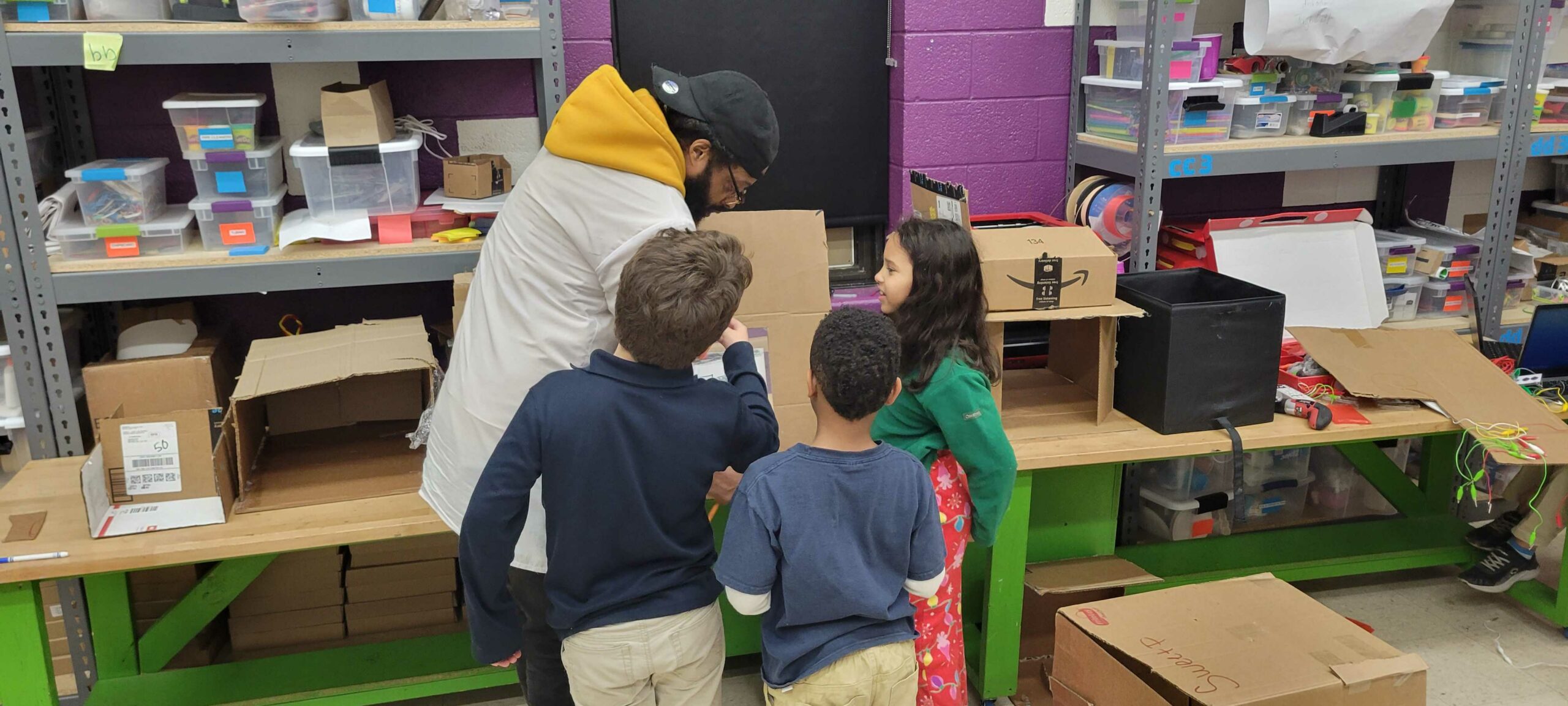
Tech Lab
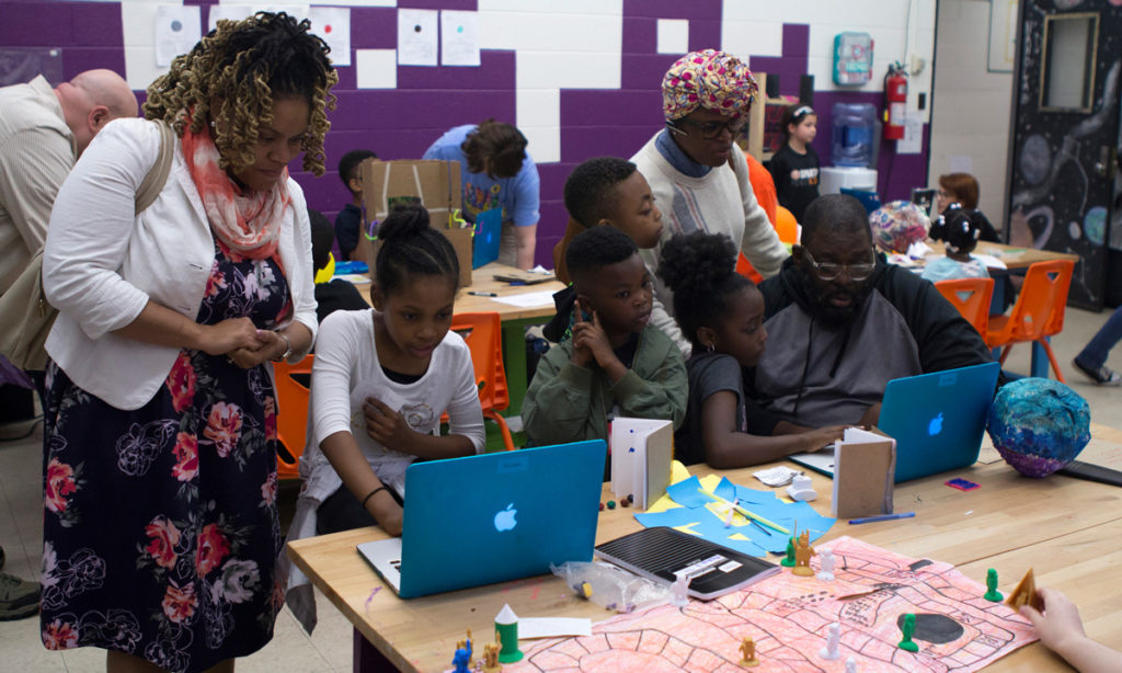
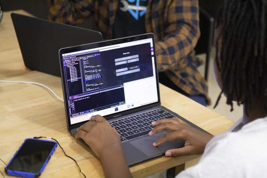
Digital Harbor Foundation operates three innovative programs that provide youth with access to tech-powered learning opportunities, support educators through high-quality training and content, and close the gap between academic innovation and local economies. These projects are grounded in local innovation that connect learning across national ecosystems
Learn more about programs for: students, educators, or organizations.
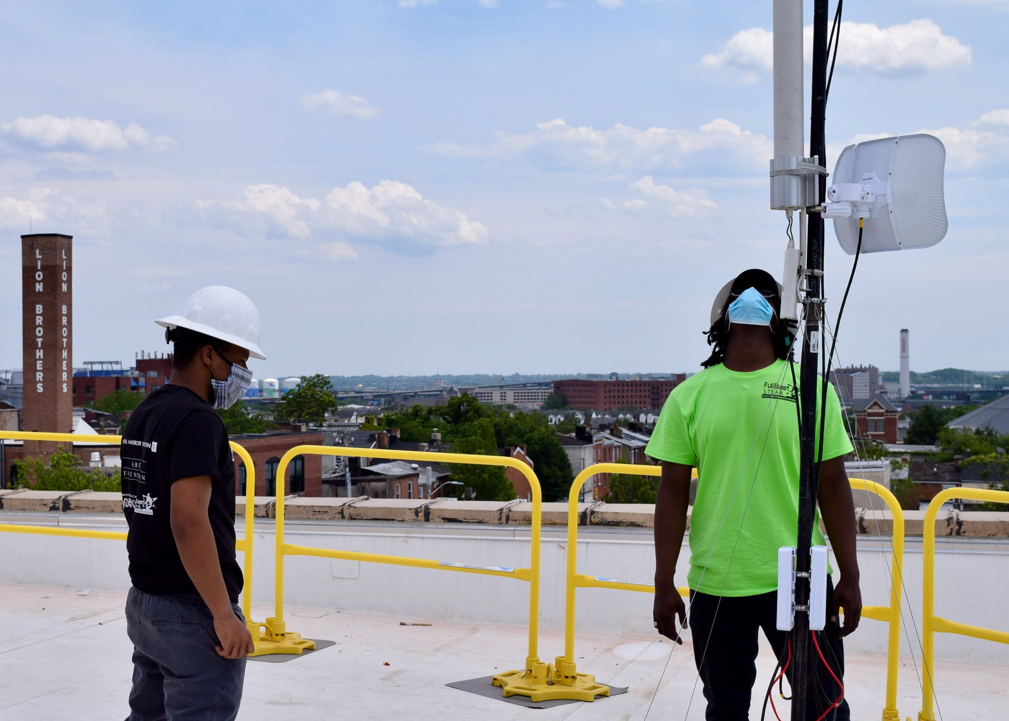
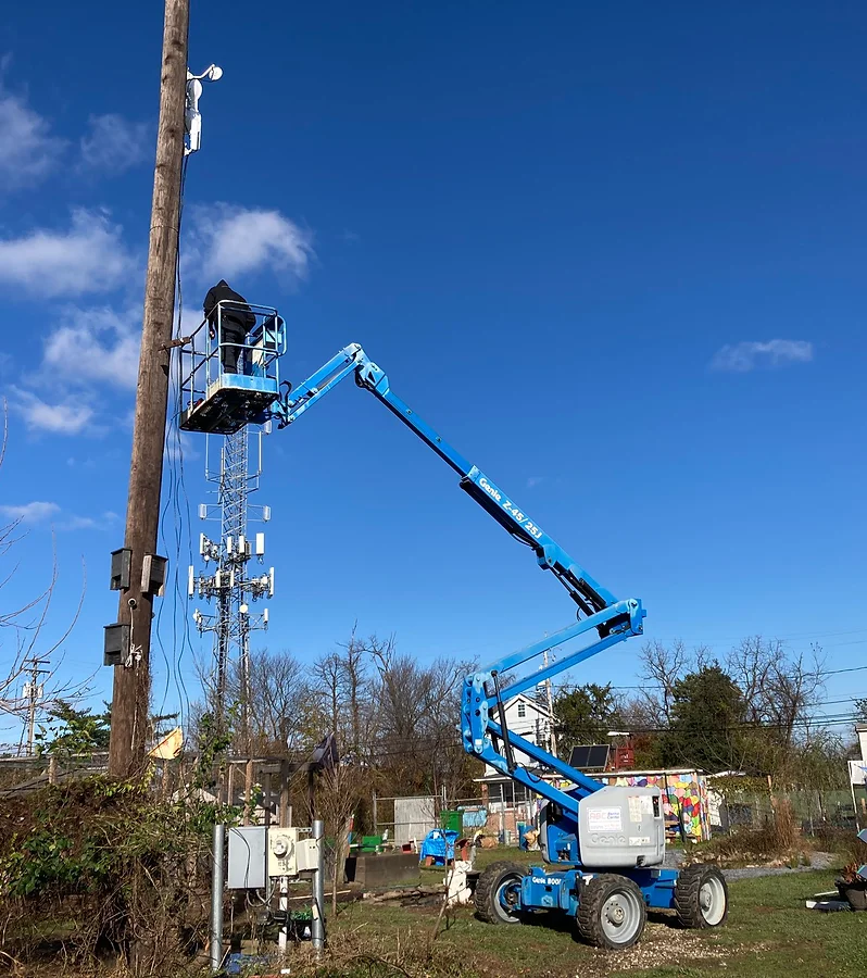
Internet Connectivity
Project Waves is committed to bridging the Digital Divide in Baltimore and beyond by developing and scaling equitable solutions that connect unserved and underserved households to the Internet and the resources to help individuals, families, and communities thrive. Initially founded in 2019 as a fiscally-sponsored effort, Project Waves has grown from beta testing, to rapid-response deployments, to a scalable model that provides the highest quality connection and speeds. Using a combination of fiber-to-the-premise and wireless technology to connect households, Project Waves envisions a world where internet access is ubiquitous and available for all.

Product Studio
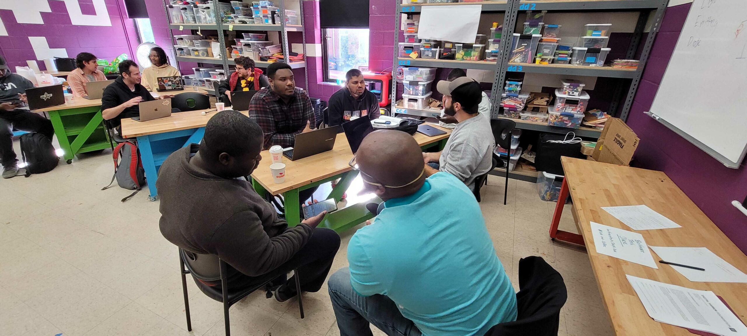
A new approach to spur the development of technology, design, and data innovations that bring together talented technologists, entrepreneurs, policy experts, and government innovators to create innovative solutions to pressing problems as identified and supported through specific efforts, often organized through a cohort-model approach.

Fiscal Sponsorship
We know there are many social innovators out there who have the passion and purpose to advance a project but lack a place and position where they can explore, develop, and launch all while being supported by an experienced team. In response to this dual condition, we have built a new model and approach that adds support on top of traditional fiscal sponsorship intended to create transformative impact.
Learn more about our innovative model and approach: